
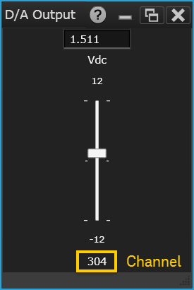
Display a slider bar to set the output voltage for D/A channels (analog outputs) on the 34907A Multi-Function Module, DAQM907A Multi-Function Module or 34980A Multi-Function Module. You can add unlimited D/A Output gadgets to the Graphics Setup tab (one channel per gadget).
Select the desired gadget window (the selected window is highlighted in blue) to display the Properties pane on the right side of the Graphics Setup tab. The available properties vary according to the type of gadget selected.
Caption - Enter the desired title to appear at the top of the current gadget window. You can specify a caption with up to 30 characters including letters, numbers, and special characters.
Select Channel - Select the desired D/A channel (channel 04 or 05) to be displayed and controlled by the current gadget (the channel number is shown at the bottom of the gadget). The drop-down list is automatically pre-populated with valid D/A channels.
Voltage - Enter the desired output voltage for the selected D/A channel (you can also set the output voltage using slider bar on the gadget itself). The two D/A channels are capable of outputting calibrated voltages between ±12 volts with 16 bits of resolution.
DAC Channel (only in DAQM907A Multi-Function Module) - Enter the desired current output for the selected D/A channel.
Minimum Value - Specify a lower voltage limit.
Maximum Value - Specify an upper voltage limit.
Number of Ticks - Specify the number of ticks on the slider.
Color - Select the desired color for the label (text), slider and slider text.
Copy Image to Clipboard - Export a screen shot of the selected display gadget to the Windows clipboard.
Right-click anywhere on the D/A Output window to display the below:
Copy Image to Clipboard - Export a screen shot of the selected display gadget to the Windows clipboard.